vfd bypass wiring diagram
K1 NO1 PB3 PB4 PB5 should be of potential free contact. 343 Wire Size 19 344 Wire Type Rating.

Vfd Bypass Star Delta Starter Control Power Wiring How To Read Electrical Wiring Diagram Youtube
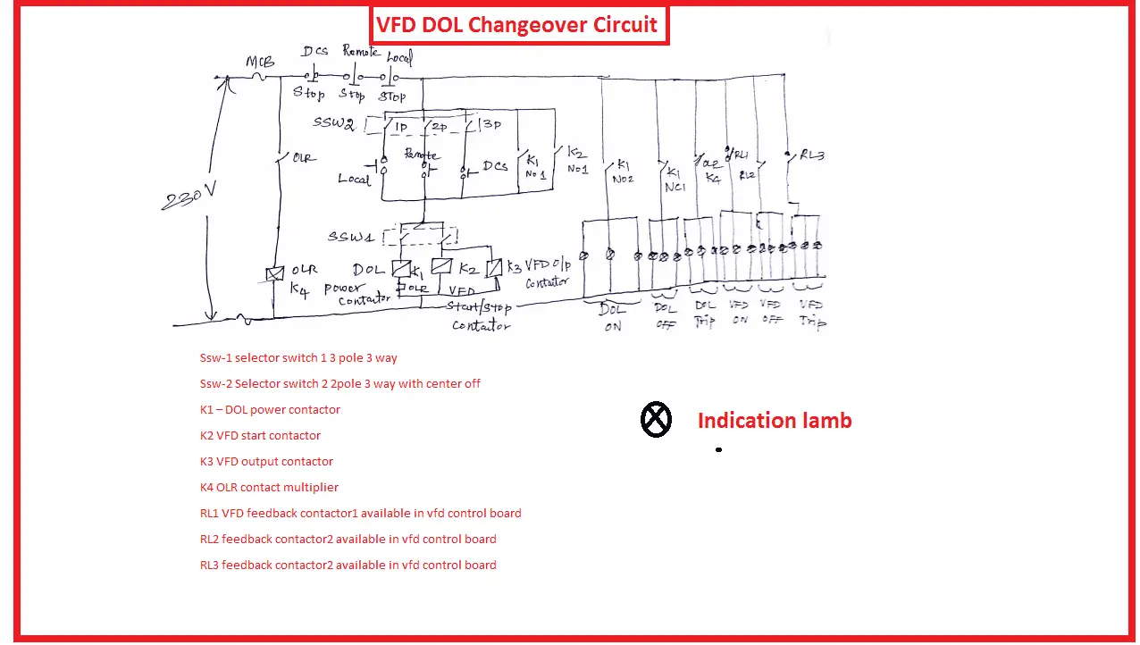
VFD DOL changeover circuit Due to some reason the dol starter or vfd got failure.

. A GENERAL Variable Frequency Drive VFD Option 2-Speed Indoor Fan Motor System The 2-Speed Indoor Fan system utilizes a Fan Speed con-trol board and Variable Frequency Drive VFD to automati-. The drive is. A variable frequency drive regulates the speed and operation of an electric motors.
By Irish Bella June 8 2019. So the bypass system is not necessary only for simple. A 3-contactor bypass adds another contact before the drive that removes power going to the VFD when placed in bypass mode.
Drive bypass cr oox run command from fire-ye controller ioa max. Saftronics Cv10 Basic Wiring Diagram. 513 06 2903 02 Rev.
Danfoss Vfd Wiring Diagram Wiring Diagram Data Schema Pioneer avic n1 wiring diagram. In bypass the motor is operated directly from line input power. Bypass 3 vfd 00x0 000x x000 4 9 6 ss1 see detail a.
Wiring Diagram Vfd With Bypass Starter. Wire and Cable Access 23 Wire Size 24 Wire Type Rating 24. Vfd wiring diagram showing power in out and control device scientific variable frequency drive for constant pressure water supply homemade hammer homemadetools net how to with plc using ladder logic instrumentationtools controlling vfds manual inputs technical articles allen bradley powerflex start stop electrical4u fans system gozuk 525 setup.
Option panel instruction manual. Ensure the motor is compatible for use with the ACH550. One of the most common functions of the option panel is to allow switching between VFD control and running in bypass.
Danfoss fc 102 hvac drive with bypass rotation check r l deppmann vfd common start stop incontrol monitoring in relay delay settings quick guide vlt micro 51 option panel instruction manual enhanced cascade controller 6000 8000 aqua pdf free vfds is 2 contactor really. VFD is the Variable Frequency Drive which converts DC power to AC power but the Bypass is an integrated bypass solution for critical applications without compromise for communications and motor protection. The isolation contactor electrically isolates the VFD during bypass operation is mechanically electrically interlocked with the bypass contactor to ensure that both cannot be closed at the same time.
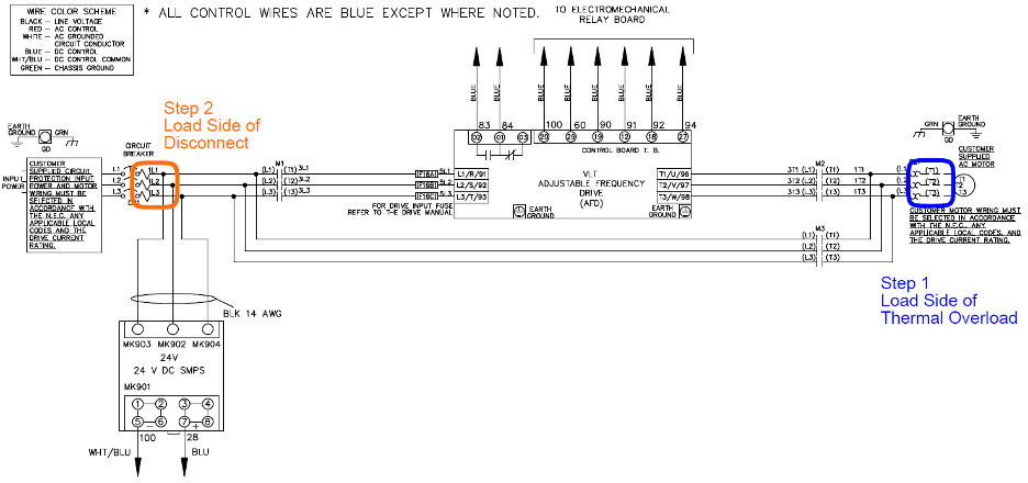
813 Typical Wiring Diagrams 9-6 Contents Vertical BypassNon Bypass Panel. Description blk 8 ga customer supplied iph 120vac 60hz cr 023a wht 16 ga disc customer analog input 4-20 ma customer anlog output shld shld 18 ga scr agnd agnd aoi agnd 24v gnd dcom die vfd 44 a 30hp 480vac dip consult manual for settings. VFD-DOL bypass wiring diagram Engineers CommonRoomWhat does a VFD doA variable frequency drive VFD is a type of motor controller that drives an electric.
The drive is programmable. A 2-contactor bypass allows a technician to flip the switch bypass the VFD and the motor will resume running at 100 percent speed. BP0056 ACH550 Input Power Ground Lug.
Vfd Bypass Wiring Diagram. Ioamax yel 16 ga ioa max. Conjunction with a Danfoss variable frequency drive VFD.
Vfd Start Stop Through Dcs Remote Local Electrical4u. Conduit kit Wiring R1R6 drives with the UL type 1 Enclosure requires a conduit kit with the following items. 343 wire size 19 344 wire type rating.
P2 Non Bypass Mechanical Layout Diagram. The following figure shows the Standard E-Bypass floor mounted wiring connection points. If in doubt contact your local ABB sales or service office.
The drive is programmable and offers many features and savings compared to operating a motor from unregulated line voltage. 112 Overview A variable frequency drive regulates the speed and operation of an electric motor. Frame 5 3 contractor with auto-bypass wiring diagrams m34046 l3140 l1140 fu4 class cc primary fuse 1 2 fu5 class cc primary fuse 2 2 1 1 1 1 250v midget secondary fuse f1u6 customer supplied freezefiresmoke interlock ffsi tb tb 3 j1 off see note 2 test bypass 3 vfd 00x0 2 3 3.
Danfoss fc 102 hvac drive with bypass rotation check r l deppmann vfd relay delay settings incontrol common start stop monitoring in quick guide vlt micro 51 option panel instruction manual mca 121 ethernet ip design 5000 manualzz bacnet enhanced cascade controller 6000 8000 aqua pdf free traditional programming basic 101 vfds is 2 contactor. 3 contactor auto-bypass wiring diagram m34046 l3140 l1140 fu4 class cc primary fuse 1 2 fu5 class cc primary fuse 2 2 1 1 1 1 250v midget secondary fuse f1u6 customer supplied freezefiresmoke interlock ffsi tb tb 3 bypass 3 vfd 3 3 bypass. Connection Diagrams Standard E-Bypass R7R8 Floor Mounted ACH550 Standard E-Bypass units are configured for wiring access from the top.
In hvac vfds is 2 contactor bypass really better than 3 2019 02 20 engineered systems magazine vfd dol changeover circuit arrangement electrical4u danfoss fc 102 drive with rotation check r l deppmann hvfdsb3c0100g332 u smartvfd 480vac 10hp graphical nema 3r enclosure. Monitoring danfoss vfd in bypass october 04. Danfoss Vfd With Bypass Wiring Diagram.
The ACH550 must be installed by a competent person. P2 Bypass Mechanical Layout Diagram 3-8 Figure 36. Connect or do wiring as per vfd side drawing you take 24 V from the VFD PCB directly.
Refer to the ACH550-UH Users Manual for control connections to the drive. Conduit box screws cover. See table 12 for their functions.
A variable frequency drive regulates the speed and operation of an electric motors. Variable Frequency Drive Bypass Energy Savings Diagram Schematic And Image 07. A typical diagram of the power circuit connection of a variable frequency drive bypass contactor is shown in the figure.
Condensate water pump Boiler DM demineralized water pump firefighting Jacky pump and all emergency pumps. In bypass the motor is operated directly from. Between VFD control and running in bypass.
In bypass the motor is operated directly from line input. By Margaret Byrd November 2 2018. By Admin July 27 2018.
In hvac vfds is 2 contactor bypass vfd dol changeover circuit danfoss fc 102 drive with three auto should you add a to your 3 pumps one china 40hp 30kw phase soft star delta. Vfd start stop wiring diagram. Modbus communications system as well as advanced motor protection when in bypass mode.
We need a good back up in order to avoid breakdown or stoppage of our industry. 2 Specifications subject to change without notice. Vfd dol changeover circuit bypass arrangement electrical4u is it possible to start 3 pumps with one when pump 1 running should put over contactor and then 2 on china 180 hp 132kw small power digital soft starter online 380v manufacturers suppliers factory aubo.
Eventually the systems should be shut down in order to safely replace the drive. When you press the on push K1 contactor will hold and K1 No1 become NC. Electronically controlled bypass additional programming and operation information is provided.
Danfoss vfd with bypass wiring diagram.

Vfd Bypass Contactor
Vfd Bypass With Star Delta Starter Control Wiring Diagram Explain Youtube
Vfd Dol Changeover Circuit Vfd Bypass Arrangement Electrical4u
Danfoss Fc 102 Hvac Drive With Bypass Rotation Check R L Deppmann